The shift from 800V to 1500V battery platforms is happening faster in commercial vehicles than most observers expected. Mining trucks, heavy haulage, electric ferries, and utility-scale energy storage are leading the transition. The reasons are simple — at 1500V you can deliver more power with thinner cables, charge faster, and pack more energy per truck without proportionally more copper.
What's less obvious is how dramatically 1500V changes the thermal management problem. A pack designed for 800V cooling will not work at 1500V. Here's why.
What changes at 1500V
More voltage means smaller current for the same power. That sounds like it should reduce heat — and at the cell level, it does. Resistive losses scale with current squared, so doubling voltage and halving current reduces I²R losses by 4×. So far, so good.
But three other things change at the same time:
•Cell count per series string roughly doubles, going from ~96 to ~192+ cells in series. More joints, more inter-cell variability, more localized hotspots.
•Insulation requirements jump non-linearly. The IEC 60664-1 spacing requirements between live conductors and ground go from 4.0 mm clearance at 800V to 8.0 mm at 1500V — and partial discharge becomes a real concern, not theoretical.
•Heat density per square meter of pack floor goes up because you're putting more energy in the same chassis space.
The net effect: a 1500V pack runs at similar overall ΔT to an 800V pack but with much tighter tolerance for cell-to-cell variation. Where ±5°C across cells was acceptable at 800V (capacity loss tolerable), at 1500V the same ±5°C drives partial-discharge events at the cell-to-busbar interface. You need ±1.5°C or better across the whole pack.
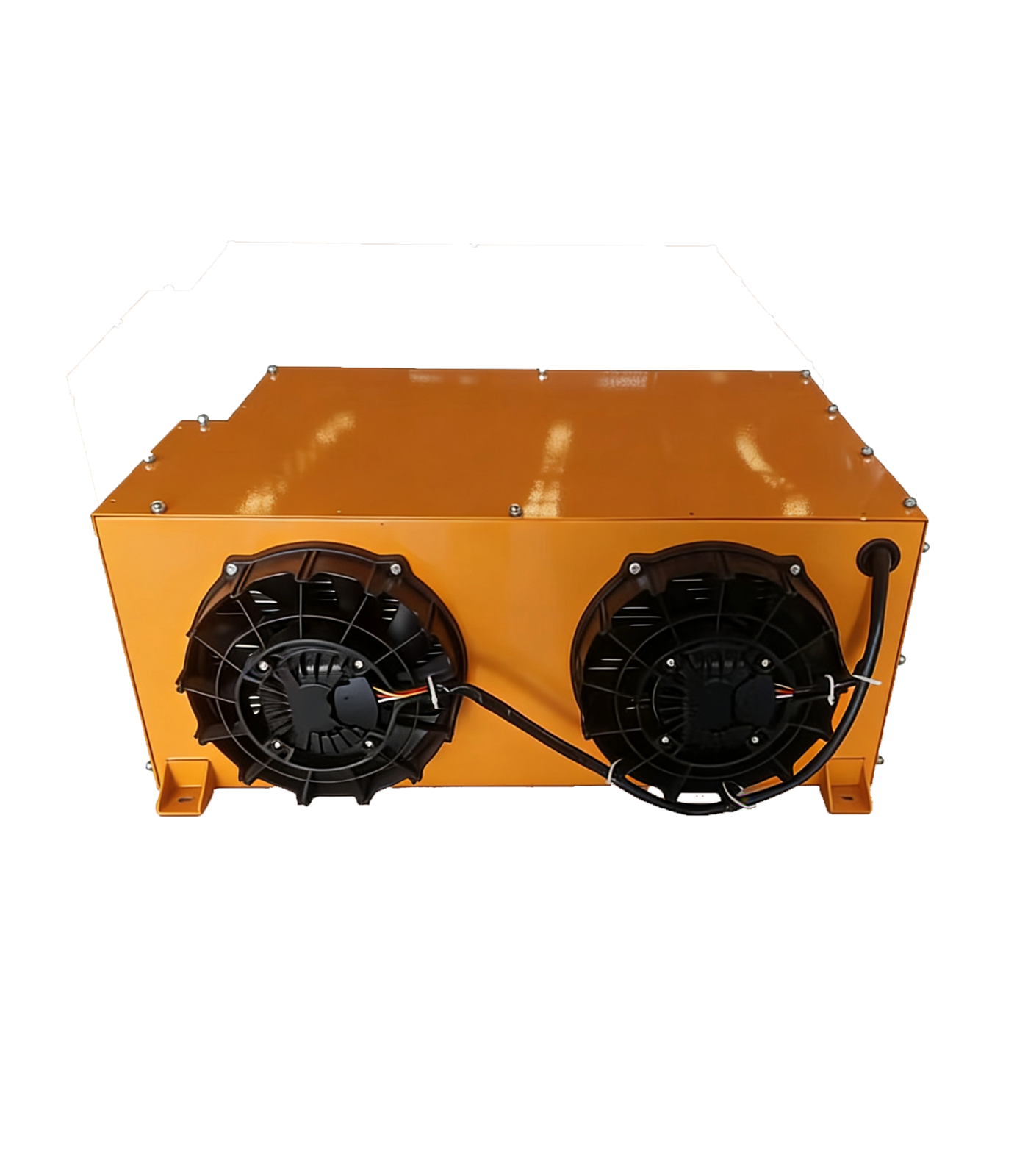
Why air cooling stops working
Air cooling works when you can flow enough air at low enough temperature past every cell. At 1500V cell densities, the geometry stops cooperating — air gaps you'd need between cells consume so much pack volume that you lose the energy density benefit of going to 1500V in the first place.
More importantly, air cooling can't deliver the temperature uniformity 1500V demands. Cells at the air-inlet end run cold; cells at the outlet end run hot. The ΔT in a forced-air pack is typically 6–8°C between best and worst cell. That's fine for 800V, fatal for 1500V partial discharge requirements.
Why basic liquid cooling also stops working
First-generation liquid cooling — cold plates under cell modules with single-zone flow — gets you to ±3°C ΔT. Better than air, but still not enough margin for 1500V.
What's needed is multi-zone liquid cooling with active flow balancing. Each cell module gets its own coolant inlet and outlet. Flow is balanced based on real-time cell temperature feedback rather than fixed orifices. The cold plate geometry uses smaller, more numerous channels to minimize inlet-to-outlet ΔT within a single module.
A Gen-3 cold plate doing this can hold ±1.5°C across the entire pack under fast-charge load. That's the threshold for safe 1500V operation.
Insulation: the part nobody talks about
At 1500V, the cooling system itself becomes part of the insulation system. Coolant lines that used to be a thermal-only concern now have to maintain electrical isolation between zones at potentials hundreds of volts apart.
This drives several design changes:
•Coolant must be deionized or use a non-conductive refrigerant. Glycol/water mixes that worked at 800V can fail isolation tests at 1500V.
•Plastic flow connectors (commonly nylon or polyamide) need higher CTI ratings (Comparative Tracking Index — IEC 60112). At 1500V, materials below CTI 600 are not acceptable.
•Cold plate-to-cell module isolation needs explicit creepage and clearance design. Sandwich insulation films must be qualified for the dielectric stress.
•Coolant manifold geometry must avoid bridging conductive paths. A poorly placed manifold becomes a 1500V leakage path.
Real deployment data
Looking at field data from 1500V deployments in mining and heavy haulage over the last 18 months:
•Trucks with first-gen liquid cooling at 1500V show ~3× the warranty rate of equivalent 800V trucks — primarily insulation failures, not cell failures.
•Trucks with multi-zone Gen-3 liquid cooling at 1500V show comparable warranty rates to 800V — the cooling system has caught up with the platform.
•The ESS sector is roughly 12 months behind heavy vehicles in this transition. Utility customers in 2026 are now specifying 1500V containers; integrators that haven't moved to multi-zone cooling are losing tenders.
What this means for sourcing
If you're spec'ing a 1500V battery pack, the cooling system spec is inseparable from the platform spec. Asking for "liquid cooling" without specifying multi-zone, ΔT target under load, CTI rating of all flow components, and creepage/clearance documentation is not enough. You'll get a Gen-1 system retrofitted onto your 1500V chassis, and the warranty rate will tell the story 18 months later.
The right vendor questions:
•Multi-zone or single-zone flow?
•ΔT under 2C fast-charge load — measured, not spec'd.
•CTI rating of all polymer components in the flow path.
•Creepage and clearance design documentation per IEC 60664-1 at 1500V working voltage.
•Field data from at least one 1500V deployment with 12+ months of operation.
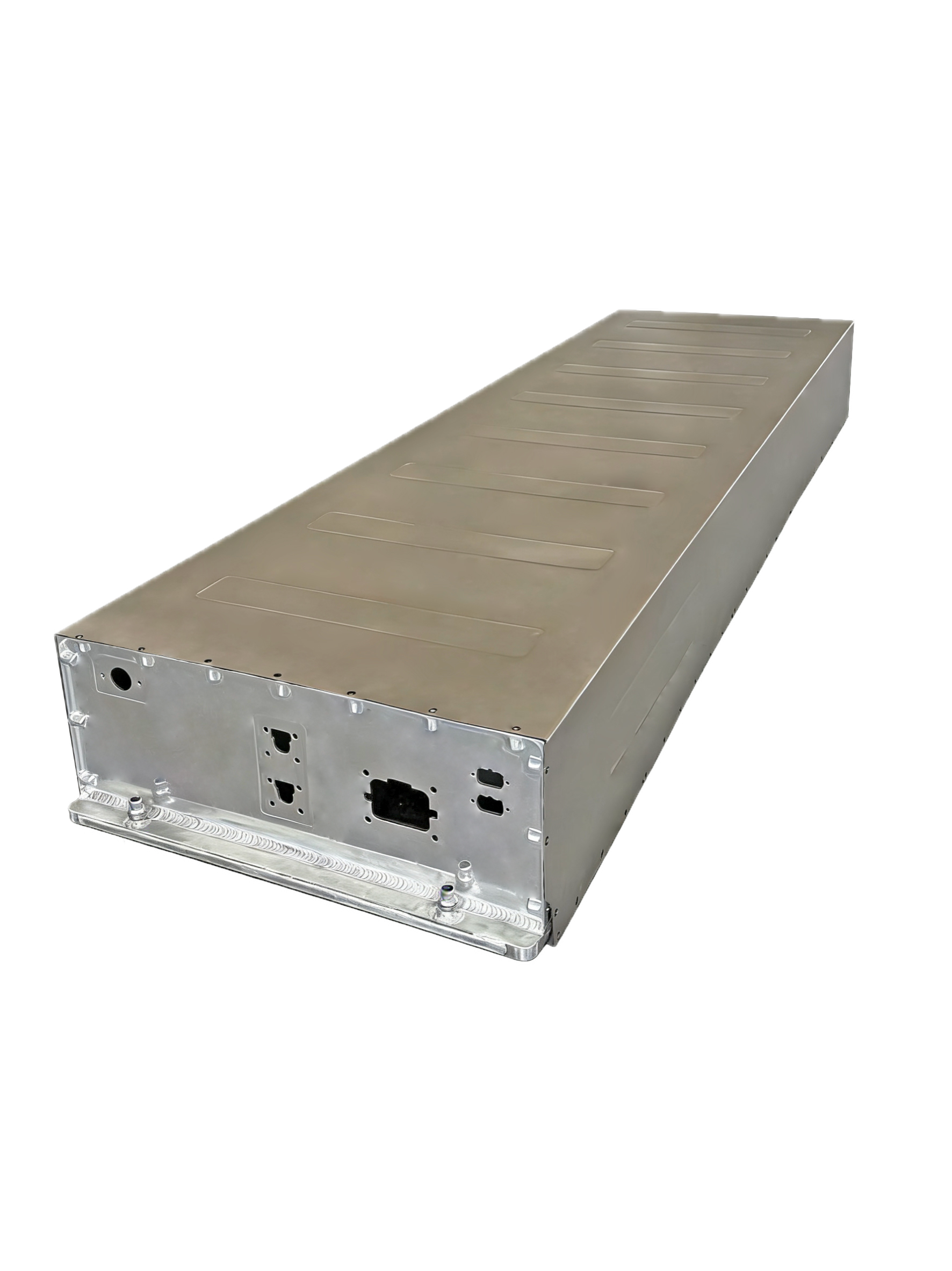
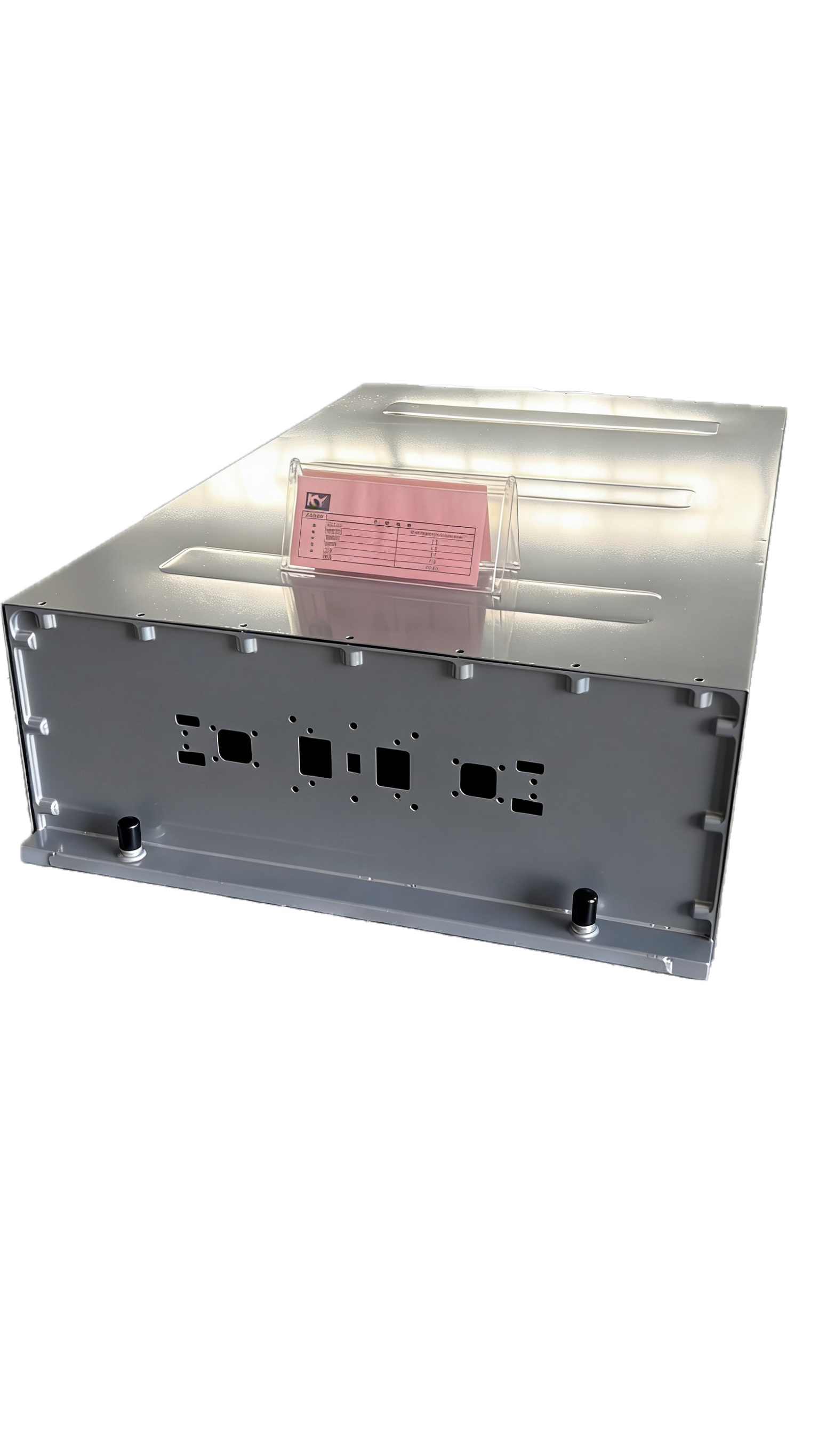
Keyuan's 1500V capability
The LC H3-Box is Keyuan's purpose-built 1500V platform — multi-zone Gen-3 cold plate architecture, balanced active flow, dedicated insulation system, integrated battery management designed for the partial-discharge sensitivity of 1500V series strings. Pack energy density 180 Wh/kg, ΔT under fast-charge load consistently under 1.5°C, all polymer flow components rated CTI 600+. We've shipped 1500V LC H3-Box units into mining and heavy-truck OEMs for 8 months as of writing — early field data is in line with the design targets.
If you're moving from 800V to 1500V and want to discuss what the cooling system needs to look like — talk to us.